Interfacing a Liquid Crystal Module
The following tables show pin assignments for typical LCD modules. There are two tables, the first for modules with less than 80 characters, the second for modules with more than 80 characters.
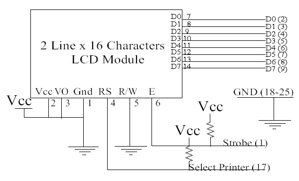
Finally, a typical electrical interface circuit is shown at the bottom of the page.
|
Pin assignment for <= 80 character displays |
||||
|
Pin number |
Symbol |
Level |
I/O |
Function |
|
1 |
Vss |
- |
- |
Power supply (GND) |
|
2 |
Vcc |
- |
- |
Power supply (+5V) |
|
3 |
Vee |
- |
- |
Contrast adjust |
|
4 |
RS |
0/1 |
I |
0 = Instruction
input |
|
5 |
R/W |
0/1 |
I |
0 = Write to LCD
module |
|
6 |
E |
1, 1-->0 |
I |
Enable signal |
|
7 |
DB0 |
0/1 |
I/O |
Data bus line 0 (LSB) |
|
8 |
DB1 |
0/1 |
I/O |
Data bus line 1 |
|
9 |
DB2 |
0/1 |
I/O |
Data bus line 2 |
|
10 |
DB3 |
0/1 |
I/O |
Data bus line 3 |
|
11 |
DB4 |
0/1 |
I/O |
Data bus line 4 |
|
12 |
DB5 |
0/1 |
I/O |
Data bus line 5 |
|
13 |
DB6 |
0/1 |
I/O |
Data bus line 6 |
|
14 |
DB7 |
0/1 |
I/O |
Data bus line 7 (MSB) |
|
Pin assignment for > 80 character displays |
||||
|
Pin number |
Symbol |
Level |
I/O |
Function |
|
1 |
DB7 |
0/1 |
I/O |
Data bus line 7 (MSB) |
|
2 |
DB6 |
0/1 |
I/O |
Data bus line 6 |
|
3 |
DB5 |
0/1 |
I/O |
Data bus line 5 |
|
4 |
DB4 |
0/1 |
I/O |
Data bus line 4 |
|
5 |
DB3 |
0/1 |
I/O |
Data bus line 3 |
|
6 |
DB2 |
0/1 |
I/O |
Data bus line 2 |
|
7 |
DB1 |
0/1 |
I/O |
Data bus line 1 |
|
8 |
DB0 |
0/1 |
I/O |
Data bus line 0 (LSB) |
|
9 |
E1 |
1, 1->0 |
I |
Enable signal row 0 & 1 |
|
10 |
R/W |
0/1 |
I |
0 = Write to LCD
module |
|
11 |
RS |
0/1 |
I |
0 = Instruction
input |
|
12 |
Vee |
- |
- |
Contrast adjust |
|
13 |
Vss |
- |
- |
Power supply (GND) |
|
14 |
Vcc |
- |
- |
Power supply (+5V) |
|
15 |
E2 |
1, 1->0 |
I |
Enable signal row 2 & 3 |
|
16 |
n.c. |
|
|
|
A typical electrical interface, along with pin assignments is shown below: