The minimum display configuration that will cause ghosting is
a two segment display where one segment is turned on and the other segment is
driven off.
If the drive frequency or voltage are increased, the "off" segment starts to
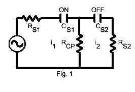
turn "on". Figure 1 is a schematic of such a configuration.
In this model RS1 and RS2
are the segment resistance of segments one and two, and CS1 and C S2
are the capacitances of segments one and two. Resistance RCP
represents the effective series resistance in the common plane circuit
consisting of contributions by the common plane electrode, the
crossover conductors, the common plane lead-out on the segment plane glass, and
the substrate to mounting pin interface.
|

|
Loop current i1 flows through the "on " segment impedances and common plane resistance RCP. Loop current i 2flows through the "off" segment impedances and RCP. The segments are modeled as capacitors with a liquid crystal dielectric, with series
resistors representing the
resistivity of the segment electrodes. In a real display, there are
contributions by both electrodes, but for this example we will use a single term
to represent both.
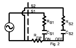
Figure 2 shows the same circuit redrawn to make the loop nature
of the circuit more evident. From this it can be seen qualitatively that the
magnitude of RCPdetermines the amount of voltage that reaches
the "off" segment and causes ghosting.
Note that because the display is always operated below the break frequency
of network RS1 - CS1, ghosting will be a function of
frequency as a result of the changing reactance of CS1with frequency.
If RCP were zero, ghosting could never occur. If RCPis
infinite, the "on" and "off" segments would be in
series sharing the drive voltage according to the relative magnitude of
their impedances. This happens when a crossover connection fails. |
 |
In a display consisting of a great number of segments,
the electrical model must be expanded to account for additional contributions to RCP
which will be different for each segment. The worst case condition for ghosting will occur
when all but one segment are turned "on" and the remaining segment is turned "off". This
maximizes the voltage drop across RCP, causing the "off" segment to see the maximum
possible voltage. If this voltage approaches the threshold voltage of the LCD fluid in the
dispay, the segment will ghost "on". |


