Overview of Adaptive Addressing
"Adaptive Addressing" for enhanced low
temperature operation.
|
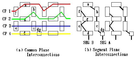
Multiplexing an LCD: The figures below show the layout of the individual segments of a 4 x 2 multiplexed display. Note that the same segments of each digit are bussed together and that common planes connect a given "group" of segments. There is therefore a 2 x 4 matrix arrangement for each character. |
 |
To turn on a given segment, say segment "f", the proper RMS voltage
waveform is applied to segment b along with common plane 1. In
general, the scheme is to scroll through the common planes in order,
and apply the correct voltage to the necessary segment plane to turn
on the desired segments. The result is a time-division multiplex of
the segments, with every pixel being driven for only 1/4 of the
time. This basic scheme is used in all multiplexed displays and is
the root of the problem.
The pixels (or segments in a segmented display) respond to the applied RMS voltage. Alt and Pleshko (1974) showed that as the multiplex ratio (i.e. the number of lines to be addressed in the matrix) increases, the contrast ratio becomes poorer until no distinction is possible between On and OFF pixels.
We could go on about the optimum drive voltage for a given mux ratio, but it is easy to see that the higher the mux rate, the less time a drive voltage is applied to any given pixel. The contrast therefore suffers greatly as the pixels naturally want to turn themselves off when the drive voltage cycles around to other common planes.
| Next Section - Threshold Driving Voltage |
If you want to cut to the chase and see how Adaptive Addressing works, go here..
