Measuring Sheet Resistance - Ohms per Square
|
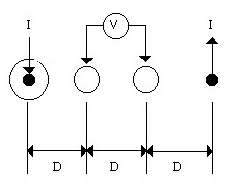
The glass used to manufacture an LCD comes from the manufacturer overcoated with an Indium Tin Oxide coating. This ITO layer is exposed, developed, and then etched to form the pattern on the finished display. The ITO has a uniform sheet resistance which is determined at the time the glass is manufactured. This layer is typically sputtered onto the glass in an extremely large multi-staged sputtering chamber. The resistance of this ITO layer is typically in a range between 40 and 120 ohms per square, as measured with a four-point probe. With a four-point probe, the resistance is measured by passing a fixed current through two points, and measuring the voltage at two other points, as shown below. A four point probe is a commercially available product, or one can easily be built.
IIn the following equations, E is the Electric field and j is the current density.
If the input current is fixed to 4.53 ma, the sheet resistance is equal to the voltage across the two test points. It can also be seen that their are no dimensions the final answer. |
||||||||||||||||||||||||||||||||||||||||||||||||||||||||||||||||||||||||||||||||||||||||||||||||||||||||||||||||||||||||||||||||||||||||||||||||||||||||||||||||||||||||||||||||||||||||||||||||||||

